Flow Test Summaries
Created to Date
9418
Enter data for up to 3 hydrants as you conduct your flow test. Record your pressure and fire hydrant flow data directly on a smartphone and our fire hydrant flow test software will calculate the distance between your hydrants.
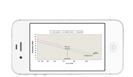
Optimize your water fire flow testing process with automatic calculations that include a graphical display of both the raw data and an associated safety factor curve. Keep your data securely in the cloud including pressures, locations, time of fire hydrant flow test and your own project specific notes.

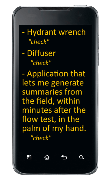
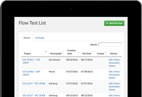
Create your professional flow test summaries minutes after the test is completed. Download summaries in a concise and effective PDF from the field. Use your default email client to send summaries straight from your smart-device.

Let our fire hydrant flow test software engine calculate everything for you automatically at the project site. Summaries come with an N1.85 graphical water supply curve, along with the rest of your NFPA-mandated data.
What is A Fire Hydrant Flow Test? A fire hydrant flow test is a process of flowing water out of at least one fire hydrant while obtaining the required pressures (static, residual, and pitot) needed to calculate the amount of water in gallons per minute (GPM) that the water system is capable of providing between the tested hydrants. FTS allows you to effectively and efficiently create a PDF report from the field in less than 5 minutes after a test is conducted.
Who Needs Fire Hydrant Flow Test Data? The following entities utilize fire hydrant flow test data: architects, civil engineers, fire protection engineers, mechanical engineers, city governments, fire departments, water purveyors, corporate and private contractors, City State and Federal municipalities, land developers, etc. The FTS report generated after each flow test can be immediately emailed from the flow test location to each stake holder as required.
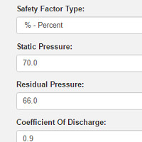
How is The Static Pressure Obtained? The static pressure is obtained by attaching a pressure gauge to a 2.5-inch outlet using a special hydrant cap. Open the hydrant valve, be sure all excess air is released, and wait for the needle on the pressure gauge to settle. This is the static pressure.
How is The Residual Pressure Obtained? When the flow fire hydrant is fully opened, note where the pressure has dropped on the pressure hydrant. This is your residual pressure.
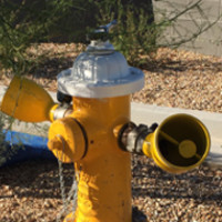
How is A Pitot Pressure Obtained? The pitot pressure is obtained by opening a hydrant valve, letting water flow directly out of an outlet, and placing a pitot tube in the center of the water stream so that a reading on the pitot gauge is obtained. This is your pitot pressure. Utilizing hand held pitot gauges, diffusers, and The Hose Monster Company™ equipment are methods that allow you to obtain the pitot pressure reading. FTS allows you to input up to 9 different pitot readings with associated coefficients of discharge per flow test, and it calculates the GPM automatically.
What is The Coefficient of Discharge? This is a number that is used when computing the flowing GPM. This number is obtained by determining what kind of hydrant outlet is utilized. FTS allows you to input any coefficient of discharge. See Figure 1 below.
Figure 1. Three General Types of Hydrant Outlets and Their Coefficients of Discharge, NFPA-291, 2016 edition.
How is The Flowing GPM (gallons per minute) calculated? The flowing GPM is calculated using the formula indicated in Figure 2. FTS will automatically calculate the flowing GPM for you after inputting the required variables (c, d, p) into the application.
Figure 2. The formula used to compute the discharge in GPM, NFPA-291, 2016 edition.
When are Additional Coefficients Applied to The Formula in Figure 2? Whenever the pumper outlet is utilized to obtain a pitot reading, an additional coefficient is applied to the equation in Figure 2 to determine the flowing gpm. The table in Figure 3 below indicates additional coefficients to utilize based on the pitot reading. FTS allows you to input additional coefficients for large orifices up to a total of 9 outlets.
Figure 3. Pumper Outlet Coefficients, NFPA-291, 2016 edition.
What is Fire-Flow and How is It Determined? Fire-Flow is the amount of available water in gallons per minute (GPM) when the residual pressure is at 20 PSI. It can be calculated by using the following equation in Figure 4 below. FTS will automatically calculate fire-flow and generate a water supply curve N1.85 graph.
Figure 4. The formula used to compute the discharge at the specified residual pressure, NFPA-291, 2016 edition.
What information, required and recommended by the IFC, NFPA, and Authorities Having Jurisdictions, is to be obtained from a fire hydrant flow test? See Figure 5 below. FTS automatically generates all this information. 
Figure 5. Water Supply Information that shall be included in a working plan submittal, NFPA-13, 2016 edition.
What time should fire hydrant flow tests be conducted? The authority having jurisdiction (AHJ) will make the final determination, however, NFPA-13, 2016 edition states “tests should be made during a period of ordinary demand”. We recommend that fire hydrant flow tests be conducted during a period of high demand. This is typically between 6am and 8am. Check with the local AHJ and/or Water Department to determine the period of high demand. FTS will autofill the time when creating a new summary. You can manually change the time if needed.
What is the recommended drop in pressure that should be obtained during a flow test? American Water Works Association (AWWA) recommends that a 10 PSI drop in pressure is obtained during a flow test. NFPA-291, 2016 edition states “to obtain satisfactory test results of theoretical calculations of expected flows or rated capacities, sufficient discharge should be achieved to cause a drop in pressure at the residual hydrant of at least a 25 percent, or to flow the total demand necessary for fire-fighting purposes”. Coordinate fully with the AHJ to make the final determination.
How many fire hydrants should I utilize during a flow test? Generally, two fire hydrants are utilized (one for the static-residual pressures and one for the flowing pitot pressure(s)). To achieve a larger drop in pressure and a larger flowing gpm, more outlets need to be flowed, and this can be done by flowing multiple fire hydrants or hydrant outlets during a test. FTS allows you to calculate up to 3 flowing hydrants (total of 9 flowing orifices).
If I’m flowing two fire hydrants during a flow test, where should the pressure hydrant be located? Per NFPA-291, 2016 edition the pressure hydrant (where the static-residual pressures are recorded) should be located between the two hydrants that are being flowed. Due to our partnership with Google Maps, FTS allows you to locate your hydrants in conjunction with Google Maps by simply dragging and dropping pins.
Should the flow hydrant or pressure hydrant be closest to the project site? The pressure hydrant should be located closest to the project site. The results obtained during a flow test evaluate the available water supply at the pressure hydrant.
How should hydrants be tested on a dead end main? The dead-end hydrant should always be flowed. The static-residual hydrant is placed such that it is located between the “large mains that constitute the immediate sources of water supply in the area” and the flow hydrant.
How often should private fire hydrants be flow tested? The International Fire Code 2015 edition states that private fire hydrants shall be flow tested annually.
How often should public fire hydrants be flow tested? NFPA-291, 2016 edition states that “public fire hydrants should be flow tested every 5 years” and that they “should be flushed at least annually”.
How long is water supply flow test data considered to be current and reliable? NFPA-13, 2016 edition states that when flow test data is to be used for system design, then the flow test data should be no more than one year old. The Authority Having Jurisdiction can supersede this requirement. FTS allows you to manually adjust the current and reliable date so that it can match AHJ requirements.
Why is it important to know the elevation of a fire hydrant? Elevations impact pressures. 0.433 PSI per foot of elevation is either gained or lost. FTS will automatically provide the hydrant elevations based on where you located your hydrant pins via integrated Google Maps.
If given the opportunity to flow either the 2.5” outlet(s) or the pumper outlet, which one is preferred? The 2.5” outlet(s) will give you a more accurate reading in most cases, as the entire cross-section of the outlet is filled by the discharge of water, whereas a pumper outlet often has a void space in the stream of discharged water. FTS web application allows you to input additional coefficients when larger outlets are flowed. Coordinate each flow test with local AHJ and water purveyor.
Where can I obtain more information about fire hydrant flow testing? Two published guidelines about fire hydrant flow testing are: NFPA-291, 2016 edition (Recommended Practice for Fire Flow Testing and Marking of Hydrants) and AWWA M17 2016 edition (Installation, Field Testing, and Maintenance of Fire Hydrants).
Utilize all adopted and/or current editions.
NFPA-291 Recommended Practice for Fire Flow Testing and Marking of Hydrants. National Fire Protection Association. 2016
NFPA-13 Standard for the Installation of Sprinkler Systems. National Fire Protection Association. 2016
M17 Fire Hydrants: Installation, Field Testing, and Maintenance, Fifth Edition. American Water Works Association. 2016
Brock, Pat D. Fire Protection Hydraulics and Water Supply Analysis. Fire Protection Publishing Department, 2012